Virtual Audio Cable (VAC)
20+ years of experience. Connects audio apps together since 1998.
Virtual Audio Cable (VAC)
20+ years of experience. Connects audio apps together since 1998.
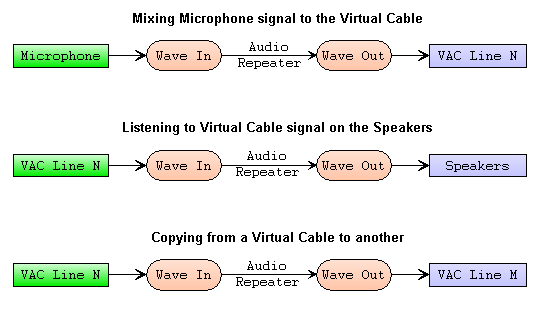
Audio Repeater is a simple application that transfers a real-time audio stream from any recording endpoint to any playback one. Audio Repeater can be used with VAC to transport audio data from a real sound card to a Virtual Cable, monitor a signal going through a Virtual Cable with a real sound card, transport audio data from between two Virtual Cables etc.
There are two versions of the application: plain (MME) and Kernel Streaming.
Plain version of Audio Repeater uses MME interface to access high-level audio endpoints. It means that playback to Virtual Cables goes via System Audio Engine layer in shared mode, so Audio Repeater cannot fully control actual audio format used for System Audio Engine pin instance creation (see audio layering issues). To access via KS interface, use Kernel Streaming version.
To supply a Virtual Cable with a real audio signal, choose a sound adapter (card) endpoint (microphone, line input or other) in the Wave In field of the Audio Repeater, and choose a Virtual Cable's endpoint in the Wave Out field. To monitor an audio signal transferred through the Virtual Cable, choose Virtual Cable's endpoint in the Wave In field and the sound adapter (card) endpoint (speakers, headphone or other) in the Wave Out field.
In simple cases, you can use the Listen feature (available since Win7) instead of Audio Repeater.
You can leave "None" in the Wave Out field. In such case, Audio Repeater will only record from the endpoint specified in Wave In field, without playing the recorded data. It can be useful for visual signal level monitoring if you don't need to pass the signal further.
In MME, endpoint name length is limited to 31 characters so you will not always see full endpoint names.
Before starting transfer with the Audio Repeater, select format parameters possibly close to formats used by other applications connected to this Virtual Cable. To eliminate redundant format conversions, pay attention to the audio layering issues.
The Channel config parameter specifies a typical channel configuration (mono, stereo, surround etc.) or a custom mode that allows you to select any channel combination.
If one of both endpoints are associated with Virtual Audio Cable (VAC) driver, you can turn on VAC clock control to eliminate clock rate difference problems.
Transfer is started as you click the Start button. Audio Repeater opens both audio endpoints and maintains a continuous data stream between them.
Gauge indicators under channel configuration checkboxes show peak signal levels in appropriate channels. Indicators are logarithmic. Levels below -6 dB are displayed in green, from -6 to -3 dB - in yellow, and levels above -3 dB are displayed in red.
The Queue gauges show the percentage of data buffer parts held in buffer queues. If a gauge goes to the right, it means that data amount if the queue is increased, and vice versa. In the most stable state, both queues are near to the full state (100%, indicators on the right).
The longer is transfer time, the larger the difference between queue sizes can be, and the higher is stream interruption probability. Side activity, such as disk read/write, application launch, high CPU load can affect stream stability.
Indicator color shows queue status: green - normal, yellow/brown - short, red - critically close to the resynchronization point.
If one of the queues is constantly getting shorter over time, it may indicate significant clock rate difference between input and output endpoints. If one or both endpoints belong to VAC driver, try to use VAC clock control.
There are two counters, Overflows and Underflows. Overflows counter is incremented when Audio Repeater has no free buffer parts for recorded data (input queue gauge comes to the left). Underflows counter is incremented when Audio Repeater has no buffer parts to play back (output queue gauge comes to the left).
Overflows and underflows can occur as a result of heavy system load (when Audio Repeater does not receive enough CPU time), clock rate difference effect etc.
Using Virtual Cable endpoints in Audio Repeater, please note that these application's overflows and underflows are opposite to cable's overflows and underflows. For example, when Audio Repeater has no free buffer to pass to cable's recording end, it registers an underflow (there are no data). On the contrary, the cable has data but cannot give them because there are no buffer parts so the cable registers an overflow (there is no room for data).
Queue exhaust and overflows/underflows may occur due to different timing event periods. Each audio device has its own time period to notify the driver and/or client application about streaming progress. For example, if the device issues a notification event each 15 milliseconds and you have specified total buffering time of 40 milliseconds in 8 parts (5 ms each), every notification will indicate that 3-4 parts are recorded/played. It is a significant portion of the entire buffer so the streaming will be rough and unstable. You will need to increase buffering time and/or number of buffer parts to smoother the stream. Unfortunately, only Virtual Cables allow to specify a timing event period; other devices don't expose this information and you should determine it by experiment.
SR fields next to overflow/underflow counters,show actual sampling rates measured during the streaming.
VAC clock fields above them show the state of VAC client clock control, if such control is used. Only a single side can use the clock control, so only one indicator can be active.
The indicator shows a rectangular label of different sizes (from a thin vertical line to a wide bar) in different positions. The position of the label indicates VAC clock factor (1 - in the middle, less than 1 - shifted to the left, greater than 1 - shifted to the right). The width of the label indicates the stability of the clock factor: a narrow label means that the factor is changed slightly, so the synchronization is reliable; a wide label means that the factor is subject to strong fluctuations, and the synchronization may become lost.
Actual values of cable client clock factor are shown by VAC Control Panel in its cable information window.
To optimize audio transfer, you can vary the buffering time (total buffer) and number of buffer parts (data blocks). The total buffering time (in milliseconds) specifies how much audio data/space is reserved to compensate for transmission/execution rate fluctuations. The larger is buffering time, the more robust is the transfer, the less is chance of sound interruption due to task switching, disk operations etc. But the larger is the buffering time, the larger is latency value, and the larger is a delay between incoming and outgoing audio data. Typical buffering times are from 50-70 to 150-200 ms. Values less than 30 ms often cause stream breaks due to internal buffering in System Audio Engine.
The number of buffer parts defines how many parts the buffering memory is divided into. The more buffer parts are used, the smoother is the transfer, especially if the total buffering time is small, and the more precise the prefill/resync features work. But large number of parts raises system overhead and use of more than 15..20 parts may not make data transfer smoother.
To avoid sound interruptions, each audio buffer part should contain at least 3..7 ms of audio. Therefore, having 100 ms total buffering time, you can divide it into 8-12 parts but for 20 ms, it is not recommended to use more than 4-8 parts.
The "Pre-fill to" field specifies amount of any queue to pre-fill before starting data transfer. As the transfer is started initially, input queue is filled to 100% (all buffer parts are queued), and data transfer starts as the specified amount of output queue is filled with recorded data. Pre-filling adds the appropriate latency but allows to keep queues away from exhausting (overflows or underflows). For small (50-200 ms) buffering, use 70-80%. For larger buffering, use 90-100% to start with both queues filled up (both indicators are on the right). Specifying zero disables queue pre-filling.
The "Resync at" field specifies amount of any queue to maintain filled by resynchronization. If queue size drops below the amount, data transfer is paused until the queue is filled up to amount specified in the "pre-fill to" field. Each resynchronization causes a single glitch (a break in audio stream) but avoids continuous glitches produced by queue exhausting. Specifying zero disables queue resynchronization.
If total buffer duration and/or number of buffer parts are small (less than 5-10 ms and/or less than 4-6 parts), resynchronization feature may work incorrectly, causing resynchronizations when they aren't required. With such small parameters, it is better to disable the feature (set the percentage to zero).
The "Resync at" control is disabled and ignored if VAC clock control is used.
The Priority field controls priority of the Audio Repeater process. The higher is priority value, the smoother a process is executing, the less time is rest for another processes. Most processes have Normal priority value, Audio Repeater has Normal value by default.
By default, Realtime priority is available only for users with administrative privileges. Be careful setting this priority value because it can cause Windows to freeze. If you want to use this priority under a limited user account, enable the "Increase scheduling priority" policy for this account (or for a group), using local security policy editor from an administrative account. The editor can be accessed from the "Administrative tools" folder in Windows Control Panel or by typing "secpol.msc" in the Start-Run dialog.
Under Windows 6.x+, Audio Repeater registers its worker thread in MMCSS to maintain its priority. If polling interval is 5 ms or greater, the "Audio" task class is used. Otherwise, the "Pro Audio" task class is used. Therefore, under Windows 6.x+, you don't need to set priority manually.
Starting from version 4.70, Virtual Audio Cable (VAC) driver supports client lock control feature. Audio Repeater can use it to eliminate the clock rate difference between the streams.
If "VAC clock mode" is "Off", VAC clock control is not used. With "Any" the application automatically selects the side that supports it (exactly one side must support clock control). If both sides support it (both input and output endpoints are exposed by VAC driver), "Input" or "Output" must specify the side that should use the clock control.
The actual status of cable clock adjustment is shown by the clock control indicator and in the Cable Information Window in VAC Control Panel.
To maintain both streams in sync, the application adjusts VAC clock rate so that both input and output buffer queues are as full as possible. Therefore, if clock control is enabled, the prefill amount is always set to 100% to start from the full output buffer, and then keep it full. The difference in buffered data amounts is used as the error value to be minimized.
Such method is effective for maintaining maximum resistance to unexpected performance fluctuations, but it may produce significant fluctuations of Virtual Cable clock rate (clock control indicator shows a wide label). Due to the peculiarities of stream processing, MME version produces stronger fluctuation than the KS one.
VAC clock rate fluctuations can be safely ignored if the streams go without overflows/underflows, and both buffer queues are almost full throughout the entire time. Since any digital audio stream assumes that data is transmitted in portions of variable size, only the average transfer rate matters.
If you see significant fluctuations of VAC clock rate, try to increase the number of buffer parts. This will reduce the size of the data portions, and may improve clock control quality. But don't forget to check the CPU time consumed by the application because data transfer and clock control operations will be performed with increased frequency.
It is important that VAC clock control feature can eliminate only the permanent clock rate difference, but cannot prevent problems that arise due to system performance fluctuations. Moreover, if significant performance fluctuations happen regularly, using VAC clock control may even worsen stability. You need to test both ways (with and without VAC clock control) to choose the best one.
You can use VAC clock control not only with another device's endpoint, but also to adjust one Virtual Cable's clock to another. It may be useful, for example, if the audio chain includes two Virtual Cables and a single endpoint of another audio device. In such case, run two instances of Audio Repeater, choose "Any" in the instance that uses the "foreign" endpoint, and choose "Input" or "Output" in another instance, for the side associated with the second Virtual Cable.
Please note that is is impossible to compensate clock rate difference between two or more audio endpoints not associated with VAC driver, because VAC driver supports clock control feature, while other audio drivers don't. So the "foreign" endpoint should be the only one in the chain, otherwise the streams cannot be synchronized for a long time.
Starting from 1803 release, Windows 10 introduces the "Microphone privacy settings", that in fact affects all recording/input endpoints. If Audio Repeater encounters an error that is usually associated with a disabled recording endpoint access, it prompts to open system's privacy settings window.
When opening a wave endpoint, Audio Repeater uses WAVEFORMATEX format descriptor if sample size if 16 bits or less and number or channels is 1 or 2. If sample size is greater than 16 bits and/or number of channels is greater than two, Audio Repeater opens the endpoint with modern WAVEFORMATEXTENSIBLE descriptor.
The Load Config and Save Config buttons allow to load or save application configuration. Save Config button creates an UTF-16 encoded file with command-line option set compatible with the /Config option. Load Config reads a file encoded in ANSI, UTF-8 or UTF-16 and interprets it as a command-line option set.
Audio Repeater accepts several command-line options, allowing to pre-configure it:
| /Input:<str> | Input (capture, recording) endpoint name |
| /Output:<str> | Output (playback, rendering) endpoint name |
| /SamplingRate:<num> | Sampling rate (samples per second) |
| /BitsPerSample:<num> | Bits per sample |
| /Channels:<num> | Number of channels |
| /ChanCfg:<str> | Channel configuration |
| /BufferMs:<num> | Total buffering duration in milliseconds |
| /BufferParts:<num> | Number of buffer parts |
| /Prefill:<percent> | Percent of each queue size to pre-fill before starting |
| /ResyncAt:<percent> | Percent of each queue size to pause until pre-filled |
| /VacClockMode:<mode> | VAC clock control mode |
| /Priority:<str> | Process priority |
| /WindowName:<str> | Name of application instance window |
| /AutoStart | Start audio transfer automatically |
| /CloseInstance:<str> | Close the specified Audio Repeater instance by its window name |
| /Config:<str> | Read options from the specified file. |
Option names are case-insensitive. <Num> means a number, <str> means a string. Specify option values exactly as you see them in Audio Repeater window, even they are cut. Endpoint names must be specified exactly as they are shown in Audio Repeater Input and Output menus. Don't specify names shown in Device Manager or in Sound/Multimedia applet.
You can set focus to "Wave in" or "Wave out" fields and press Ctrl-C to copy endpoint name to the clipboard. Then you can paste it to a command line or batch file.
If the string contains spaces or other special characters, enclose it in double quotemarks ("). To avoid name matching problems, leading/trailing spaces are stripped, space groups between words are replaced with a single space. To insert a quotemark, specify two consecutive quotemarks in the string.
If you want to enter a command line from a console and a string contains national characters that don't exist in a console code page, create a command (batch) file, placing the command line into it, and insert CHCP command before the command line. See Windows Help and Support for CHCP command description. Save this file in UTF-8 encoding to allow the command interpreter (cmd.exe) to recognize it.
With /Input and /Output options, you can specify endpoint numbers as #n, where n is a number in Audio Repeater endpoint list, starting from zero. This number is one greater than internal MME numbers because MME uses numbers starting from zero for usual endpoints, and -1 for the default endpoint. Audio Repeater uses 0 for the default endpoint, and numbers starting from 1 for others. To use no endpoint (output only), specify a dash (#-).
The custom channel configuration option has the following format:
/ChanCfg:custom=<num>
where <num> is a hexadecimal channel mask as defined for the KSAUDIO_CHANNEL_CONFIG.
For example, to configure Audio Repeater with "Virtual Cable 1" as input endpoint, "USB Speakers" as output one, sampling rate 48000, 16 bits per sample, two channels (stereo), command line parameters should be the following (a single, continuous line):
/Input:"Virtual Cable 1" /Output:"USB Speakers" /SamplingRate:48000 /BitsPerSample:16 /Channels:2
/CloseInstance option has a special meaning. Instead of specifying a parameter for a newly started Audio Repeater instance, it instructs to close an existing instance that has a specified window name (specified earlier by /WindowName option). If used, it must be the only option in command line. If a named window exists (even if hidden), the window close message is sent to it. The option can be used to close any application window, not only Audio Repeater's.
/Config option instructs to read contents of a file with the specified path and interpret it as option list. A file may contain other /Config options, and so on. Options read from the file are processed as if they were specified instead the /Config option. Semicolon can be used to add a comment to the end of line, or to "comment out" entire lines or their trailing parts.
You can create a shortcut for Audio Repeater or invoke it from a batch (command) file to achieve better automation. See Windows Help and Support center for details (type "create shortcut" in the Search field to see how to create and edit shortcuts, type "batch files" to see how to use batch files).
To create a shortcut, locate either Audio Repeater executable file in VAC installation directory or default Audio Repeater shortcut in VAC folder in the Start Menu. Command-line parameters should be appended (space separated) to the executable file path in the "Target" field.
In a batch file, use Start command (type "start /?" in the Windows Command Prompt window for explanation) to start several instances simultaneously.
To run Audio Repeater instances automatically after a logon, place shortcuts to the Startup folder of the Start Menu. See Windows Help and Support for details.
Audio Repeater supports tray minimizing. To restore, left-click the icon. To open a context menu, right-click the icon.
To start Audio Repeater minimized to the tray, use either the start command with /min option (see "start /?" for details) or a shortcut with the "Minimized" running mode.
This Audio Repeater version is intended to access low-level waveform audio endpoints via through high-performance and low-latency Kernel Streaming (WDM/KS). It looks and works like standard MME version but has some important differences.
Using KS version, please note it accesses waveform pins directly, not using System Audio Engine or other intermediate layers. It means no format conversion is performed by System Audio Engine, only device and/or its driver format conversion features will work, if any.
Additionally, KS version allocates a pin instance directly, so if device driver does not allow multiple pin instances, this pin cannot be used simultaneously by several applications and/or Windows itself. As long you keep opened a pin in KS version, you will be unable to open another instance of the same pin, even via other Windows audio interfaces.
See audio layering issues for details.
Therefore, don't use KS version unless clearly understand how it works and how it differs from the basic MME version.
Each entry of "Wave in" and "Wave out" lists represents a single KS pin. Since most KS filters don't provide names for their render/capture pins, filter names are shown instead. If a filter has more than a single render/capture pin, pin number prefix is added to a name to distinguish different pins.
Please note that KS device/pin names are usually different from MME endpoint names. For example, Virtual Cable pin names are Virtual Cable N for both capture (recording) and render (playback) sides. To specify a pin name in the command file, copy the name from KS version window, not MME one.
KS version allows to specify input and output channel configurations separately. This feature can be used with VAC cable channel scatter/gather feature or for other channel mapping purposes. See the example of scatter/gather feature usage.
Queue indicators in Kernel Streaming version behave like in MME version. The input queue is fully filled at the start but the output queue is filled up to the pre-fill point to minimize clock rate difference effect. In the most stable state, both queue indicators should be on the right (queues are filled up).
KS version supports all MME command-line options, and some additional ones:
| /ChanCfgIn:<str> | Input channel configuration |
| /ChanCfgOut:<str> | Output channel configuration |
| /PacketModeIn:on|off | Use packet mode for input pin, if supported |
| /PacketModeOut:on|off | Use packer mode with output pin, if supported |
Depending on the application version, "/BufferParts" or "/Buffers" option is used to specify the number of buffer parts.
During the transfer, KS version displays some statistics:
To the right of input/output pin names, KS protocol type is displayed (legacy or RT Audio). RT Audio usually has less latency than legacy buffering but not all drivers support this mode. If the driver supports both RT Audio and legacy modes, RT Audio is used.
The "Buffer duration" field shows actual audio buffer duration. For legacy protocol, it is always equal to the specified total duration. For RT Audio protocol, actual duration may be greater due to rounding enforced by the system.
Audio drivers support only a limited set of formats (format ranges) at WDM/KS level. If a given format is not supported by device pins, Audio Repeater displays an error message, listing format ranges supported by the driver for the pin. But these ranges represent only a "best case" support; in particular adapter configurations, actually accepted ranges may be narrower than reported.
Please note that Kernel Streaming version interacts directly with an audio device driver and uses a different communication technique than standard Windows audio subsystem. KS protocols and properties are not fully documented by Microsoft so implementation of some functions is based only on experimental results. Most audio drivers, even WHQL certified, are tested only using standard Windows audio subsystem requests. On non-standard requests, such drivers may generate errors and even BSODs. For example, some Realtek WHQL-certified drivers generate BSODs if a sampling rate less than 8000 is selected for a capture operation.
Such driver behavior is definitely incorrect and should not be considered as Audio Repeater's problem because a well-built driver never causes BSODs. If a driver other than VAC causes a BSOD, please contact driver's vendor instead of complaining to Audio Repeater.
For RT Audio protocol, a circular buffer should be allocated. If number of buffer parts is 2, Audio Repeater tries to allocate a buffer with notifications and, if successful, resulting buffer size/duration is usually close to the requested. If number of parts is different, or the driver doesn't support buffer notifications, resulting buffer size may be significantly greater due to rounding enforced by the system, which increases the latency. Therefore, if you want to reduce the latency as much as possible, and the pins support notification (event driven) mode (PKEY_AudioEndpoint_Supports_EventDriven_Mode), try to set number of buffer parts to 2, and check the actual buffer duration.
When the number of buffer parts is 2 and notification/packet modes are supported by the pin, Audio Repeater uses packet mode protocol to inform the driver about read/write progress on the application's side. This doesn't add efficiency and/or stability but allows to determine potential glitches (overflows/underflows). But please note that registered overflows/underflows themselves don't necessary mean audible glitches, and vice versa.
This parameter allows the application to use packet mode feature if supported by the driver. This mode doesn't improve streaming efficiency or stability, it just allows to detect potential buffering problems (glitches).
Using this mode, the application, together with the driver, maintains synchronized data counters. If synchronization is broken, both the application and the driver register a glitch (buffer overflow or underflow). So packet mode is useful for controlling stream stability with relatively long buffers (50 ms or more) and when the system is not significantly loaded.
With short buffers (less than 20-30 ms) and/or heavy system loads (even short-term), when the application-to-driver interaction is "on the edge", barely keeping up with each other, packet mode may start to detect false glitches. A detected glitch may cause re-synchronization that adjusts stream buffer positions, causing an audible gap, click or pop. In such case, it is recommended to turn packet mode off.
Using the packet mode, the application limits the size of data portions copied from the input buffer to the output one, to the packet size. With very short buffers (less than 5-7 ms), it may negatively affect the performance and stability.